
Page 63 - newDATAmagazine® | 15>07>2022
P. 63
newDATA
MAGAZINE
C+L-band node architectures
for the horseshoe topology
This article analyzes some of the node These filters typically provide high channel
architectures for the C+L bands, considering isolation contributing to low ILs, usually ~0.6
metro networks based on the horseshoe dB, but introduce a band gap between the C
topology. These nodes are typically based on and L bands, typically between 300 and 500
two main blocks, one for the C-band and GHz, which reduces the capacity of the fiber.
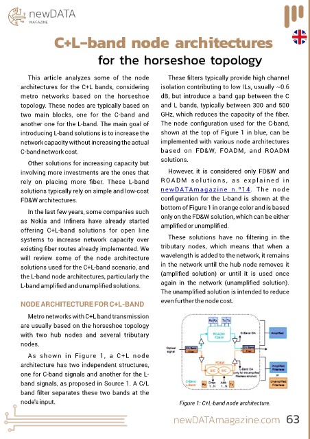
another one for the L-band. The main goal of The node configuration used for the C-band,
introducing L-band solutions is to increase the shown at the top of Figure 1 in blue, can be
network capacity without increasing the actual implemented with various node architectures
C-band network cost. based on FD&W, FOADM, and ROADM
solutions.
Other solutions for increasing capacity but
involving more investments are the ones that However, it is considered only FD&W and
rely on placing more fiber. These L-band R O A D M s o l u t i o n s , a s e x p l a i n e d i n
solutions typically rely on simple and low-cost newDATAmagazine n.º14. The node
FD&W architectures. configuration for the L-band is shown at the
bottom of Figure 1 in orange color and is based
In the last few years, some companies such
as Nokia and Infinera have already started only on the FD&W solution, which can be either
amplified or unamplified.
offering C+L-band solutions for open line
systems to increase network capacity over These solutions have no filtering in the
existing fiber routes already implemented. We tributary nodes, which means that when a
will review some of the node architecture wavelength is added to the network, it remains
solutions used for the C+L-band scenario, and in the network until the hub node removes it
the L-band node architectures, particularly the (amplified solution) or until it is used once
L-band amplified and unamplified solutions. again in the network (unamplified solution).
The unamplified solution is intended to reduce
NODE ARCHITECTURE FOR C+L-BAND even further the node cost.
Metro networks with C+L band transmission
are usually based on the horseshoe topology
with two hub nodes and several tributary
nodes.
As shown in Figure 1, a C+L node
architecture has two independent structures,
one for C-band signals and another for the L-
band signals, as proposed in Source 1. A C/L
band filter separates these two bands at the
node's input. Figure 1: C+L-band node architecture.
newDATAmagazine.com 63