
Page 64 - newDATAmagazine® | 15>07>2022
P. 64
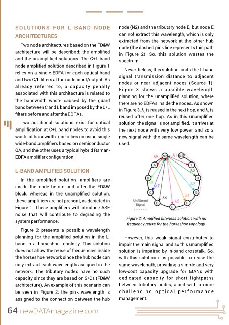
SOLUTIONS  FOR  L-BAND  NODE                          node (N2) and the tributary node E, but node E
         ARCHITECTURES                                         can not extract this wavelength, which is only
                                                               extracted from the network at the other hub
            Two node architectures based on the FD&W           node (the dashed pink line represents this path
         architecture  will  be  described:  the  amplified     in  Figure  2).  So,  this  solution  wastes  the
         and the unamplified solutions. The C+L band            spectrum.
         node amplified solution described in Figure 1
                                                                  Nevertheless, this solution limits the L-band
         relies on a single EDFA for each optical band         signal  transmission  distance  to  adjacent
         and two C/L filters at the node input/output. As       nodes  or  near  adjacent  nodes  (Source  1).
         already  referred  to,  a  capacity  penalty          Figure  3  shows  a  possible  wavelength
         associated with this architecture is related to       planning  for  the  unamplified  solution,  where
         the  bandwidth  waste  caused  by  the  guard         there are no EDFAs inside the nodes. As shown

         band between C and L band imposed by the C/L          in Figure 3, λ  is reused in the next hop, and λ  is
                                                                                                             1
                                                                            2
         filters before and after the EDFAs.                    reused after one hop. As in this unamplified
            Two  additional  solutions  exist  for  optical    solution, the signal is not amplified, it arrives at
         amplification at C+L band nodes to avoid this          the next node with very low power, and so a
         waste of bandwidth: one relies on using single        new signal with the same wavelength can be
         wide-band amplifiers based on semiconductor            used.

         OA, and the other uses a typical hybrid Raman-
         EDFA amplifier configuration.


         L-BAND AMPLIFIED SOLUTION

            In  the  amplified  solution,  amplifiers  are
         inside  the  node  before  and  after  the  FD&W

         block,  whereas  in  the  unamplified  solution,
         these amplifiers are not present, as depicted in
         Figure 1. These amplifiers will introduce ASE
         noise  that  will  contribute  to  degrading  the

         system performance.                                       Figure 2: Amplified filterless solution with no
                                                                   frequency reuse for the horseshoe topology.
            Figure  2  presents  a  possible  wavelength

         planning  for  the  amplified  solution  in  the  L-      However,  this  weak  signal  contributes  to
         band  in  a  horseshoe  topology.  This  solution     impair the main signal and so this unamplified
         does not allow the reuse of frequencies inside        solution is impaired by in-band crosstalk. So,
         the horseshoe network since the hub node can          with  this  solution  it  is  possible  to  reuse  the
         only extract each wavelength assigned in the          same wavelength, providing a simple and very

         network.  The  tributary  nodes  have  no  such       low-cost  capacity  upgrade  for  MANs  with
         capacity since they are based on S/Cs (FD&W           dedicated  capacity  for  short  lightpaths
         architecture). An example of this scenario can        between  tributary  nodes,  albeit  with  a  more

         be  seen  in  Figure  2:  the  pink  wavelength  is   c h a l l e n g i n g   o p t i c a l   p e r f o r m a n c e
         assigned to the connection between the hub            management.


     64 newDATAmagazine.com